


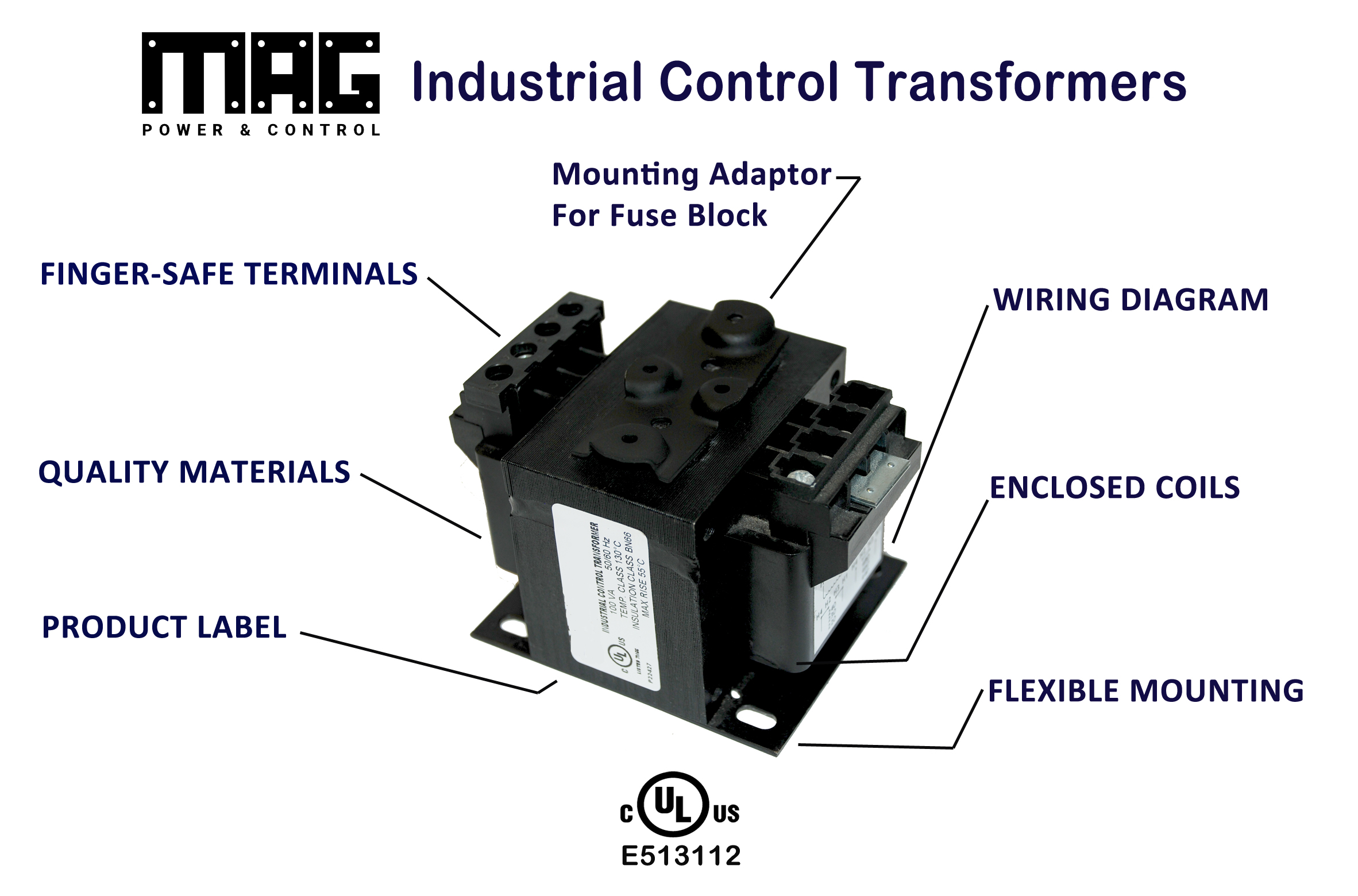
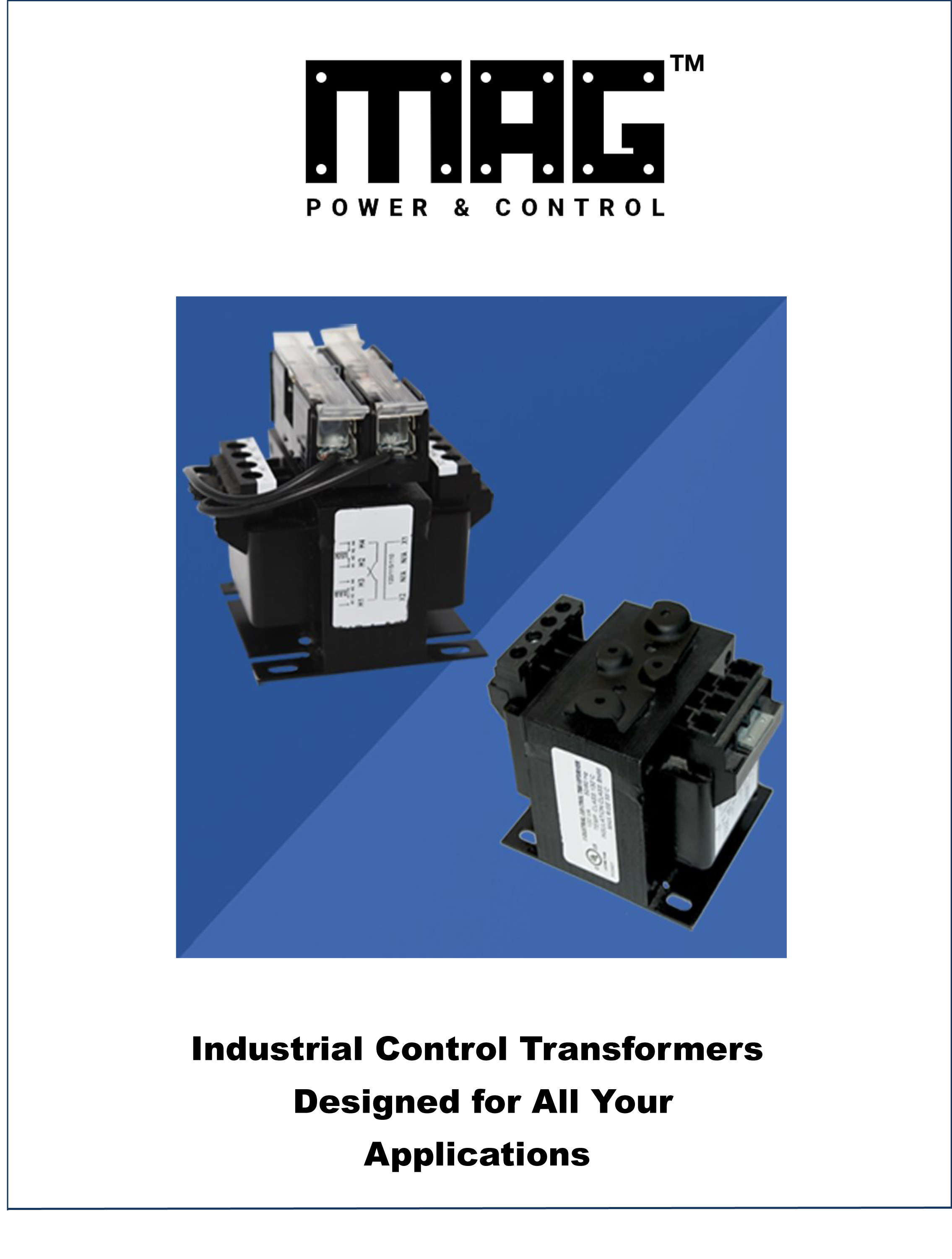
Industrial Control Transformers
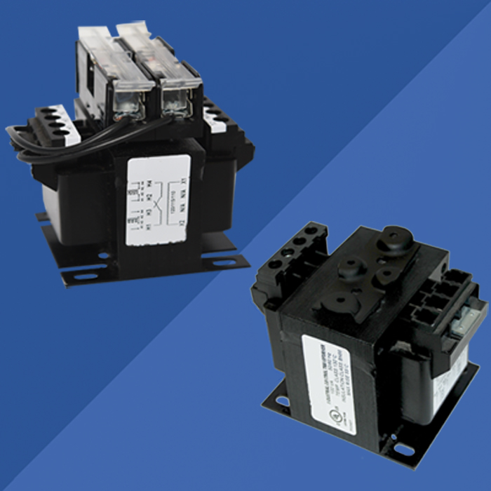
MAG Power & Control offers a wide selection of Industrial Control Transformers to meet your needs. MPC transformers are used with a wide variety of electromagnetic devices, such as relays, solenoids, motor starters, control panels and contractors.
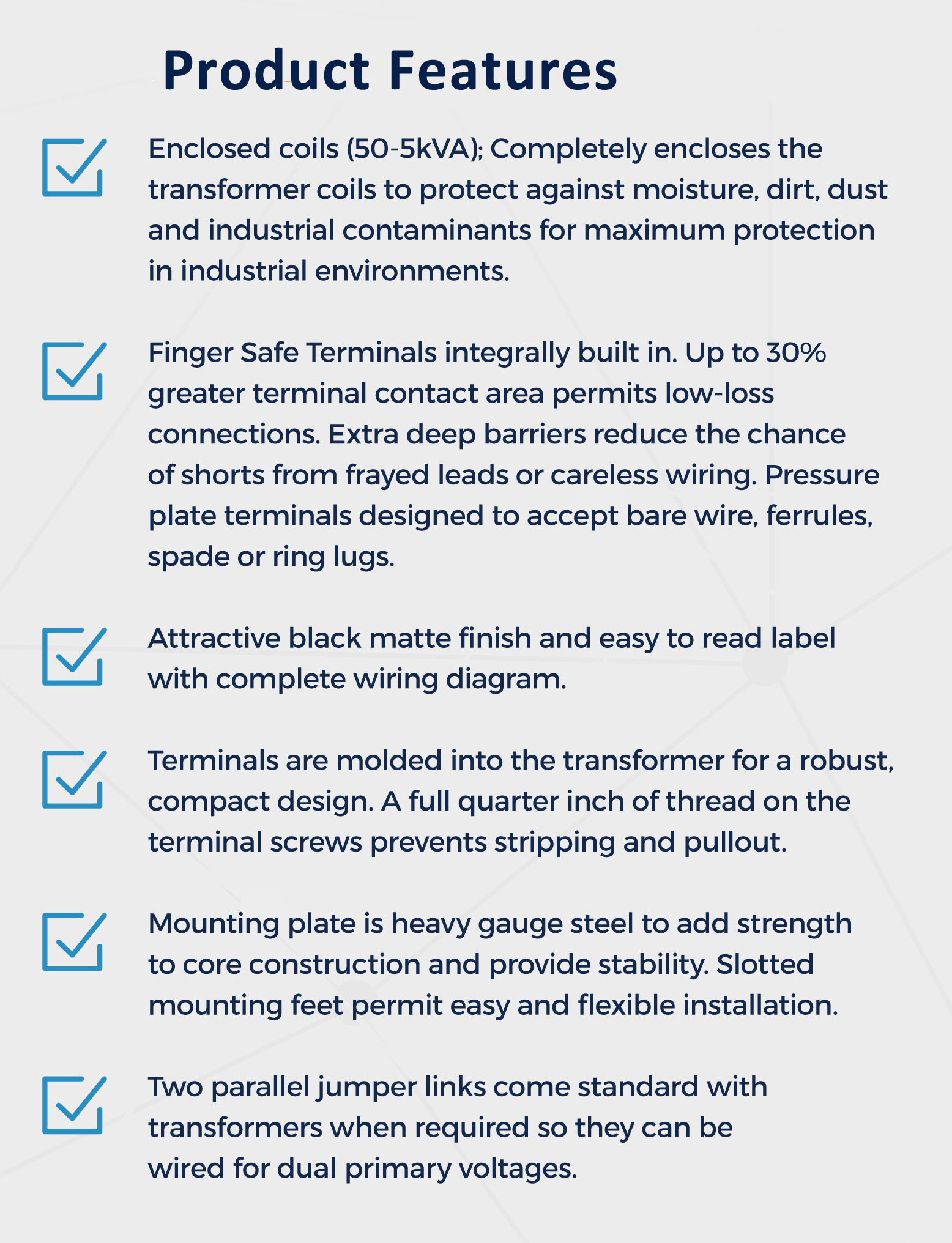
Features include:
- Finger-safe terminals
- Enclosed coils 50-5000 VA
- Secondary Voltage 24 to 240V
- In stock in Charlotte, NC
- Heavy duty steel mounting plate
- Mounting adapter for fuse blocks
- Fusing Options
- Meets or exceeds, UL, CE, CSA,
NEMA, ANSI,
and OSHA standards
Industrial Control Transformer Categories
| DM Series | |
| PRI | SEC |
| 220 x 440 | 110 |
| 230 x 460 | 115 |
| 240 x 480 | 120 |
| BS Series | |
| PRI | SEC |
| 240 x 480 | 24 |
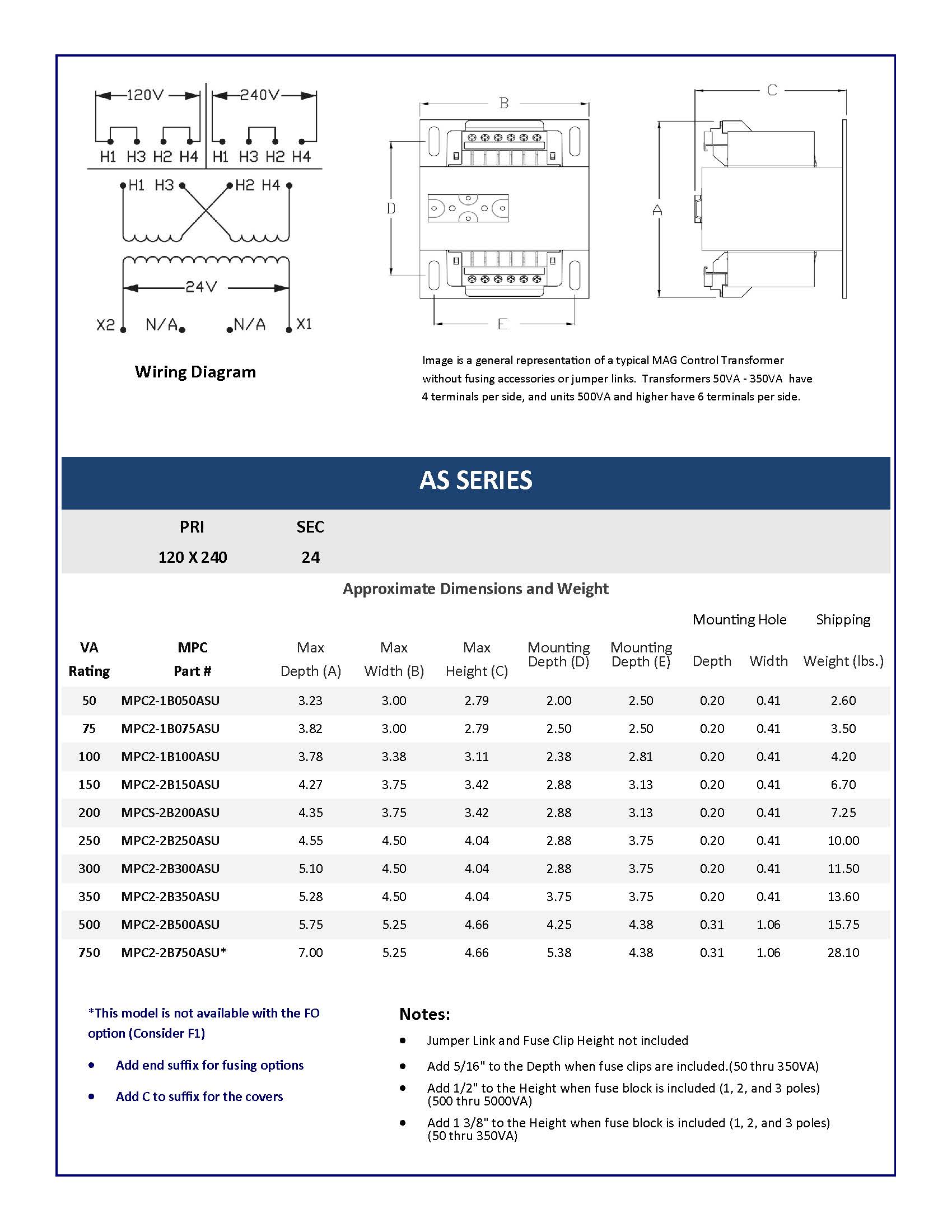
| AS Series | |
| PRI | SEC |
| 120 x 240 | 24 |
| DS Series | |
| PRI | SEC |
| 115 x 230 | 24 |
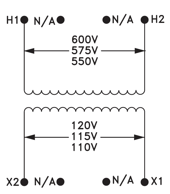
| EM Series | |
| PRI | SEC |
| 550 | 110 |
| 575 | 115 |
| 600 | 120 |
| WQ Series | |
| PRI | SEC |
| 208/277 | 120 |
| CM Series | |
| PRI | SEC |
| 200/220/440 | 110 |
| 208/230/460 | 115 |
| /240/480 | 120 |
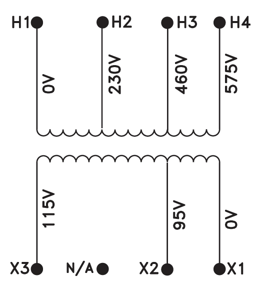
| FN Series | |
| PRI | SEC |
| 230/460/575 | 95/115 |
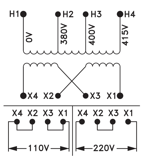
| ZP Series | |
| PRI | SEC |
| 380/400/415 | 110 X 220 |
| CL Series | |
| PRI | SEC |
| 200/220/440 | 23/110 |
| 208/230/460 | 24/115 |
| /240/480 | 25/120 |
| BA Series | |
| PRI | SEC |
| 240 x 480 | 120 x 240 |
|
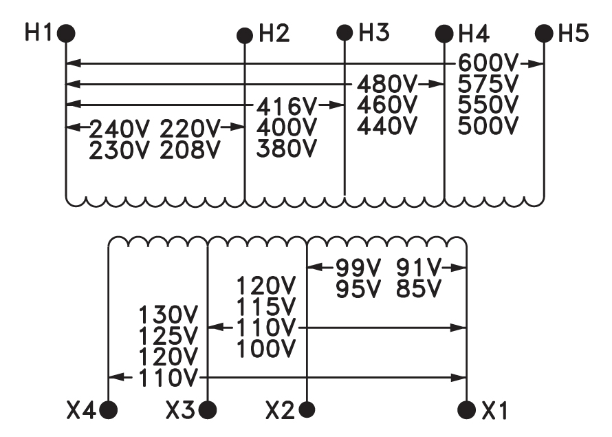
ZZ Series (Universal Voltage) |
|
| PRI | SEC |
| 600/480/416/240 | 99/120/130 |
| 575/460/400/230 | 95/115/125 |
| 550/440/380/220 | 91/110/120 |
| 500/ / /208 | 85/100/110 |
| DY Series | |
| PRI | SEC |
| 220 x 440 | 110 x 220 |
| 230 x 460 | 115 x 230 |
| 240 x 480 | 120 x 240 |
| RA Series | |
| PRI | SEC |
| 240/347/380 | 120 x 240 |
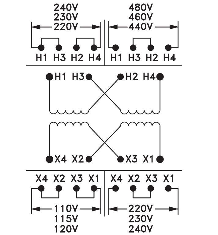
DM SERIES
PRI SEC
220 X 440
110
230 X 460
115
240 X 480
120
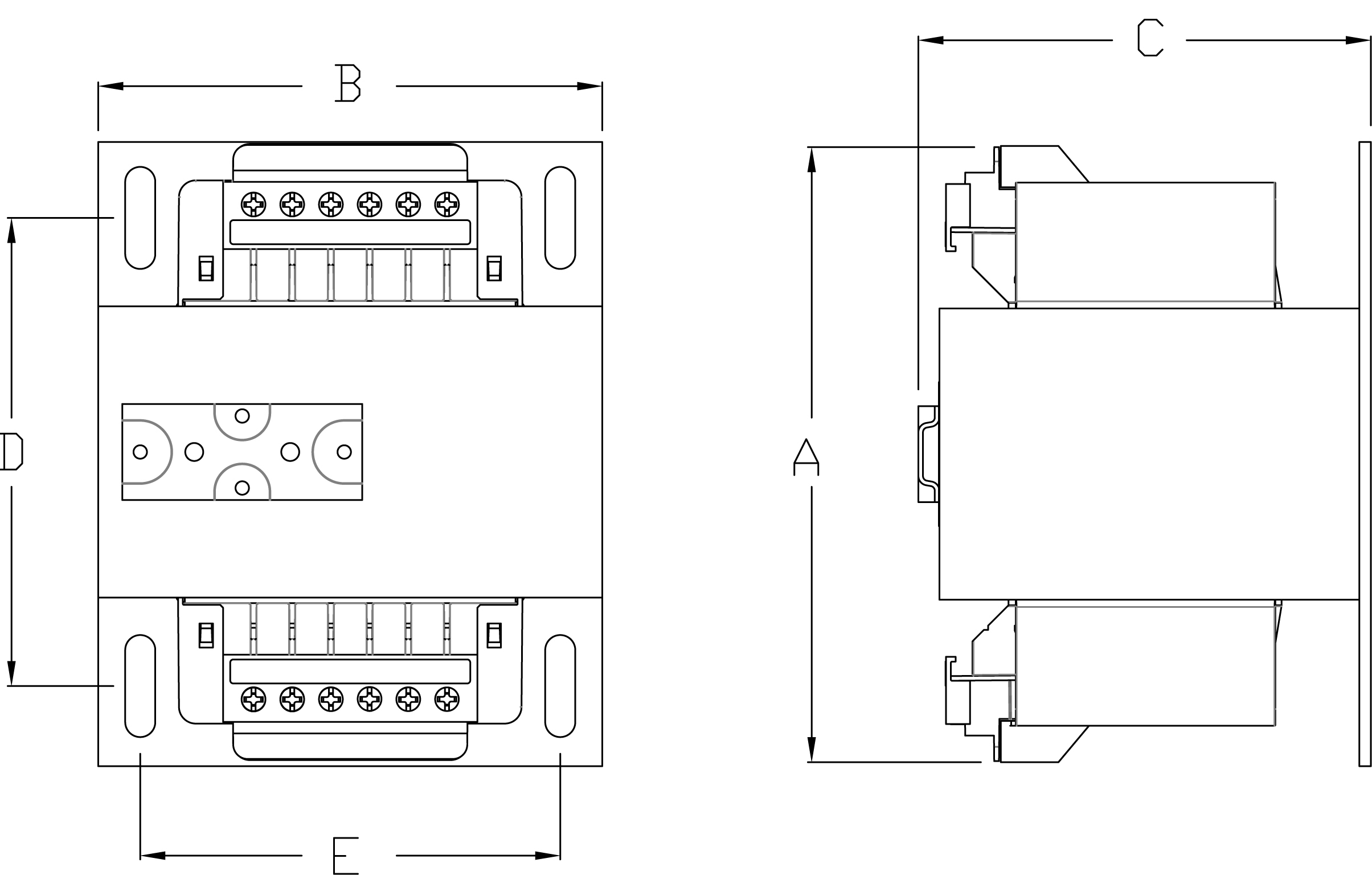
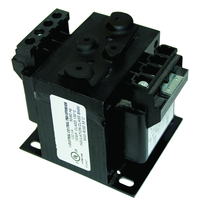
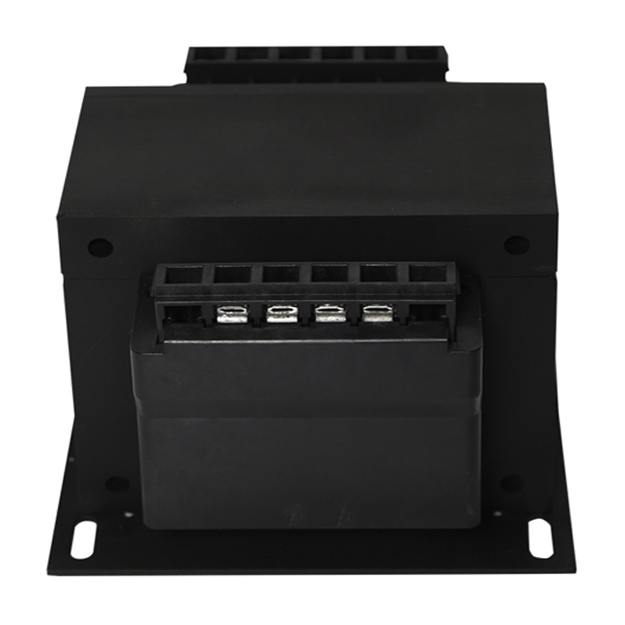
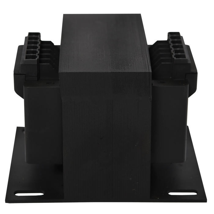
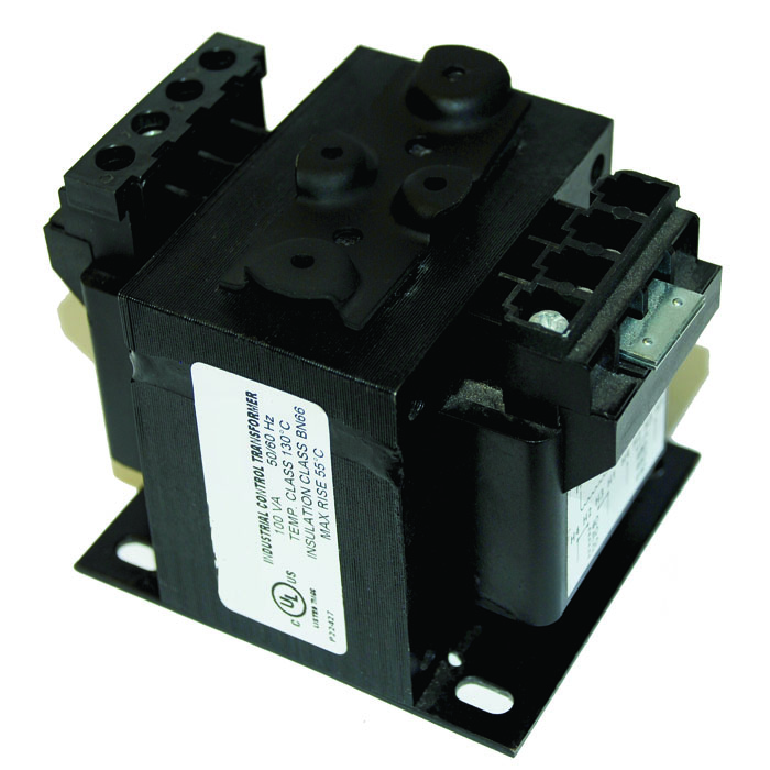
Image is a general representation of a typical MPC Transformer without fusing accessories or jumper links. Transformers 50VA - 350 VA have 4 terminals per side and units 500Va and higher have 6 terminals per side.
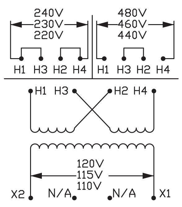
Wiring Diagram
| Approximate Dimensions and Weight | |||||||||
| Mounting Hole | Shipping | ||||||||
| VA Rating |
MPC Model # |
Max |
Max Width (B) |
Max Height (C) |
Mounting Depth (D) |
Mounting Depth (E) |
Depth | Width | Weight (lbs.) |
| 50 | MPC2-1B050DMU-FO | 3.32 | 3.00 | 2.79 | 2.00 | 2.50 | 0.20 | 0.41 | 2.60 |
| 75 | MPC2-1B075DMU-FO | 3.82 | 3.00 | 2.79 | 2.50 | 2.50 | 0.20 | 0.41 | 3.50 |
| 100 | MPC2-1B100DMU-FO | 3.78 | 3.38 | 3.11 | 2.38 | 2.81 | 0.20 | 0.41 | 4.20 |
| 150 | MPC2-2B150DMU-FO | 4.27 | 3.75 | 3.42 | 2.88 | 3.13 | 0.20 | 0.41 | 6.70 |
| 200 | MPC2-2B200DMU-FO | 4.05 | 4.50 | 4.04 | 2.50 | 3.75 | 0.20 | 0.41 | 8.50 |
| 250 | MPC2-2B250DMU-FO | 4.55 | 4.50 | 4.04 | 2.88 | 3.75 | 0.20 | 0.41 | 10.00 |
| 300 | MPC2-2B300DMU-FO | 4.55 | 4.50 | 4.04 | 3.25 | 3.75 | 0.20 | 0.41 | 11.30 |
| 350 | MPC2-2B350DMU-FO | 5.28 | 4.50 | 4.04 | 3.75 | 3.75 | 0.20 | 0.41 | 13.60 |
| 500 | MPC2-2B500DMU-FO | 5.75 | 5.25 | 4.66 | 4.25 | 4.38 | 0.31 | 1.06 | 15.75 |
| 750 | MPC2-2B750DMU-FO | 7.00 | 5.25 | 4.66 | 5.38 | 4.38 | 0.31 | 1.06 | 28.10 |
| 1,000 | MPC2-1H1K0DMU-FO | 6.61 | 7.00 | 5.65 | 4.00 | 6.13 | 0.31 | 1.06 | 29.80 |
| 1,500 | MPC2-1H1K5DMU-FO | 7.62 | 7.00 | 5.65 | 4.50 | 6.13 | 0.31 | 1.06 | 30.00 |
| 2,000 | MPC2-1H2K0DMU-FO | 8.37 | 7.00 | 5.43 | 5.13 | 6.13 | 0.31 | 1.06 | 38.00 |
| 3,000 | MPC2-1H3K0DMU-*** | 7.82 | 9.00 | 7.62 | 4.25 | 6.50 | 0.44 | 1.00 | 53.00 |
| 5,000 | MPC2-1H5K0DMU-*** | 9.06 | 9.00 | 7.62 | 7.25 | 7.50 | 0.44 | 1.00 | 89.00 |
|
***No Fuse Kit is available for this model -Change end suffix for added options -Add C to suffix for covers |
|||||||||
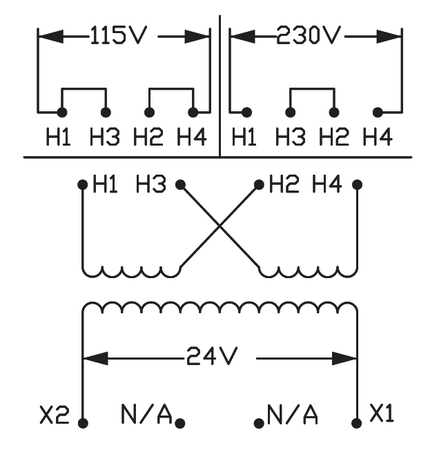
BS SERIES
PRI SEC
240 X 480
24
Image is a general representation of a typical MPC Transformer without fusing accessories or jumper links. Transformers 50VA - 350 VA have 4 terminals per side and units 500Va and higher have 6 terminals per side.
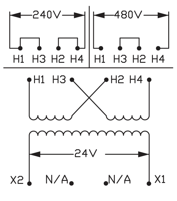
Wiring Diagram
| Approximate Dimensions and Weight | |||||||||
| Mounting Hole | Shipping | ||||||||
| VA Rating |
MPC Model # |
Max |
Max Width (B) |
Max Height (C) |
Mounting Depth (D) |
Mounting Depth (E) |
Depth | Width | Weight (lbs.) |
| 50 | MPC2-1B050BSU-FO | 3.32 | 3.00 | 2.79 | 2.00 | 2.50 | 0.20 | 0.41 | 2.60 |
| 75 | MPC2-1B075BSU-FO | 3.82 | 3.00 | 2.79 | 2.50 | 2.50 | 0.20 | 0.41 | 3.50 |
| 100 | MPC2-1B100BSU-FO | 3.78 | 3.38 | 3.11 | 2.38 | 2.81 | 0.20 | 0.41 | 4.20 |
| 150 | MPC2-2B150BSU-FO | 4.27 | 3.75 | 3.42 | 2.88 | 3.13 | 0.20 | 0.41 | 6.70 |
| 200 | MPC2-2B200BSU-FO | 4.35 | 3.75 | 3.42 | 2.88 | 3.13 | 0.20 | 0.41 | 7.25 |
| 250 | MPC2-2B250BSU-FO | 4.55 | 4.50 | 4.04 | 2.88 | 3.75 | 0.20 | 0.41 | 10.0 |
| 300 | MPC2-2B300BSU-FO | 5.10 | 4.50 | 4.04 | 2.88 | 3.75 | 0.20 | 0.41 | 11.50 |
| 350 | MPC2-2B350BSU-FO | 5.28 | 4.50 | 4.04 | 3.75 | 3.75 | 0.20 | 0.41 | 13.60 |
| 500 | MPC2-2B500BSU-FO | 5.75 | 5.25 | 4.66 | 4.25 | 4.38 | 0.31 | 1.06 | 15.75 |
| 750 | MPC2-2B750BSU-** | 7.00 | 5.25 | 4.66 | 5.38 | 4.38 | 0.31 | 1.06 | 28.10 |
|
**This model is not available with the FO
option (Consider F1) -Change end suffix for added options -Add C to suffix for covers |
|||||||||
| AS SERIES | ||||||||||
|
|
 |
||||||||
|
Image is a general
representation of a typical MPC transfromer without fusing accessories or jumper links. Transformers 50VA - 350VA have 4 terminals per side and units 500VA and higher have 6 terminals per side. |
Wiring Diagram | ||||||||
| Approximate Dimensions and Weight | |||||||||
| Mounting Hole | Shipping | ||||||||
| VA Rating |
MPC Model # |
Max |
Max Width (B) |
Max Height (C) |
Mounting Depth (D) |
Mounting Depth (E) |
Depth | Width | Weight (lbs.) |
| 50 | MPC2-1B050ASU-FO | 3.32 | 3.00 | 2.79 | 2.00 | 2.50 | 0.20 | 0.41 | 2.60 |
| 75 | MPC2-1B075ASU-FO | 3.82 | 3.00 | 2.79 | 2.50 | 2.50 | 0.20 | 0.41 | 3.50 |
| 100 | MPC2-1B100ASU-FO | 3.78 | 3.38 | 3.11 | 2.38 | 2.81 | 0.20 | 0.41 | 4.20 |
| 150 | MPC2-2B150ASU-FO | 4.27 | 3.75 | 3.42 | 2.88 | 3.13 | 0.20 | 0.41 | 6.70 |
| 200 | MPC2-2B200ASU-FO | 4.35 | 3.75 | 3.42 | 2.88 | 3.13 | 0.20 | 0.41 | 7.25 |
| 250 | MPC2-2B250ASU-FO | 4.55 | 4.50 | 4.04 | 2.88 | 3.75 | 0.20 | 0.41 | 10.00 |
| 300 | MPC2-2B300ASU-FO | 5.10 | 4.50 | 4.04 | 2.88 | 3.75 | 0.20 | 0.41 | 11.50 |
| 350 | MPC2-2B350ASU-FO | 5.28 | 4.50 | 4.04 | 3.75 | 3.75 | 0.20 | 0.41 | 13.60 |
| 500 | MPC2-2B500ASU-FO | 5.75 | 5.25 | 4.66 | 4.25 | 4.38 | 0.31 | 1.06 | 15.75 |
| 750 | MPC2-2B750ASU-*** | 7.00 | 5.25 | 4.66 | 5.38 | 4.38 | 0.31 | 1.06 | 28.10 |
|
**This model is not available with the FO
option (Consider F1) -Change end suffix for added options -Add C to suffix for covers |
|||||||||
| BA SERIES | ||||||
|
|
|
 |
||||
|
Image is a general
representation of a typical MPC transfromer without fusing accessories or jumper links. Transformers 50VA - 350VA have 4 terminals per side and units 500VA and higher have 6 terminals per side. |
Wiring Diagram | ||||
| Approximate Dimensions and Weight | |||||||||
| Mounting Hole | Shipping | ||||||||
|
VA Rating |
MPC Model # |
Max |
Max Width (B) |
Max Height (C) |
Mounting Depth (D) |
Mounting
Depth (E) |
Depth | Width | Weight (lbs.) |
| 50 | MPC2-1B050BAU-** | 3.41 | 3.00 | 2.79 | 2.00 | 2.50 | 0.20 | 0.4 | 2.60 |
| 75 | MPC2-1B075BAU-** | 3.91 | 3.00 | 2.79 | 2.50 | 2.50 | 0.20 | 0.41 | 3.50 |
| 100 | MPC2-1B100BAU-** | 3.86 | 3.38 | 3.10 | 2.38 | 2.81 | 0.20 | 0.41 | 4.20 |
| 150 | MPC2-2B150BAU-** | 4.36 | 3.75 | 3.41 | 2.88 | 3.13 | 0.20 | 0.41 | 6.70 |
| 200 | MPC2-2B200BAU-** | 4.14 | 4.50 | 4.04 | 2.50 | 3.75 | 0.20 | 0.41 | 8.50 |
| 250 | MPC2-2B250BAU-** | 4.64 | 4.50 | 4.04 | 2.88 | 3.75 | 0.20 | 0.41 | 10.00 |
| 300 | MPC2-2B300BAU-** | 4.64 | 4.50 | 4.04 | 3.25 | 3.75 | 0.20 | 0.41 | 11.30 |
| 350 | MPC2-2B350BAU-** | 5..37 | 4.50 | 4.04 | 3.75 | 3.75 | 0.20 | 0.41 | 13.60 |
| 500 | MPC2-2B500BAU-FO | 5.75 | 5.25 | 4.66 | 4.25 | 4.38 | 0.31 | 1.06 | 17.25 |
| 750 | MPC2-2B750BAU-FO | 6.74 | 5.25 | 4.66 | 5.38 | 4.38 | 0.31 | 1.06 | 28.10 |
| 1,000 | MPC2-1H1K0BAU-FO | 7.01 | 7.00 | 5.65 | 5.38 | 4.38 | 0.31 | 1.06 | 29.80 |
| 1,500 | MPC2-1H1K5BAU-FO | 8.00 | 7.00 | 5.65 | 4.50 | 6.13 | 0.31 | 1.06 | 30.00 |
| 2,000 | MPC2-1H2K0BAU-FO | 8.76 | 7.00 | 5.65 | 5.13 | 6.13 | 0.31 | 1.06 | 38.00 |
| 3,000 | MPC2-1H3K0BAU-*** | 8.14 | 9.00 | 7.62 | 4.25 | 6.50 | 0.44 | 1.00 | 53.00 |
| 5,000 | MPC2-1H5K0BAU-*** | 9.14 | 9.00 | 7.62 | 7.25 | 7.50 | 0.44 | 1.00 | 89.00 |
| **This model is not available with
the FO option (Consider F1) ***No Fuse Kit is available for this model -Change end suffix for added options -Add C to suffix for covers |
|||||||||
| Approximate Dimensions and Weight | |||||||||
| Mounting Hole | Shipping | ||||||||
| VA Rating |
MPC Model # |
Max |
Max Width (B) |
Max Height (C) |
Mounting Depth (D) |
Mounting Depth (E) |
Depth | Width | Weight (lbs.) |
| 50 | MPC2-1B050WQU-FO | 3.23 | 3.00 | 2.79 | 2.00 | 2.50 | 0.20 | 0.4 | 2.60 |
| 75 | MPC2-1B075WQU-FO | 3.73 | 3.00 | 2.79 | 2.50 | 2.50 | 0.20 | 0.41 | 3.50 |
| 100 | MPC2-1B100WQU-FO | 3.69 | 3.38 | 3.11 | 2.38 | 2.81 | 0.20 | 0.41 | 4.20 |
| 150 | MPC2-2B150WQU-FO | 4.17 | 3.75 | 3.42 | 2.88 | 3.13 | 0.20 | 0.41 | 6.70 |
| 200 | MPC2-2B200WQU-FO | 3.96 | 4.50 | 4.04 | 2.88 | 3.75 | 0.20 | 0.41 | 8.50 |
| 250 | MPC2-2B250WQU-FO | 4.47 | 4.50 | 4.04 | 2.88 | 3.75 | 0.20 | 0.41 | 10.00 |
| 300 | MPC2-2B300WQU-FO | 4.47 | 4.50 | 4.04 | 3.25 | 3.75 | 0.20 | 0.41 | 11.30 |
| 350 | MPC2-2B350WQU-FO | 5.19 | 4.50 | 4.04 | 3.75 | 3.75 | 0.20 | 0.41 | 13.60 |
| 500 | MPC2-2B500WQU-FO | 5.17 | 5.25 | 4.66 | 4.25 | 4.38 | 0.20 | 0.41 | 15.75 |
| 750 | MPC2-2B750WQU-FO | 6.42 | 5.25 | 4.66 | 5.38 | 4.38 | 0.20 | 0.41 | 28.10 |
| CM SERIES | ||||||||||
|
|
 |
||||||||
|
Image is a general
representation of a typical MPC transfromer without fusing accessories or jumper links. Transformers 50VA - 350VA have 4 terminals per side and units 500VA and higher have 6 terminals per side. |
Wiring Diagram | ||||||||
| Approximate Dimensions and Weight | |||||||||
| Mounting Hole | Shipping | ||||||||
| VA Rating |
MPC Model # |
Max |
Max Width (B) |
Max Height (C) |
Mounting Depth (D) |
Mounting Depth (E) |
Depth | Width | Weight (lbs.) |
| 50 | MPC2-1B050CMU-FO | 3.23 | 3.00 | 2.79 | 2.00 | 2.50 | 0.20 | 0.41 | 2.60 |
| 75 | MPC2-1B075CMU-FO | 3.73 | 3.00 | 2.79 | 2.50 | 2.50 | 0.20 | 0.41 | 3.50 |
| 100 | MPC2-1B100CMU-FO | 3.69 | 3.38 | 3.11 | 2.38 | 2.81 | 0.20 | 0.41 | 4.20 |
| 150 | MPC2-2B150CMU-FO | 4.17 | 3.75 | 3.42 | 2.88 | 3.13 | 0.21 | 0.41 | 6.70 |
| 200 | MPC2-2B200CMU-FO | 3.96 | 4.50 | 4.04 | 2.88 | 3.75 | 0.20 | 0.41 | 8.50 |
| 250 | MPC2-2B250CMU-FO | 4.47 | 4.50 | 4.04 | 3.25 | 3.75 | 0.20 | 0.41 | 10.00 |
| 300 | MPC2-2B300CMU-FO | 4.47 | 4.50 | 4.04 | 3.25 | 3.75 | 0.20 | 0.41 | 11.30 |
| 350 | MPC2-2B350CMU-FO | 5.19 | 4.50 | 4.04 | 3.75 | 3.75 | 0.20 | 0.41 | 13.60 |
| 500 | MPC2-2B500CMU-FO | 5.17 | 5.25 | 4.66 | 5.38 | 4.38 | 0.31 | 1.06 | 16.00 |
| 750 | MPC2-2B750CMU-FO | 6.42 | 5.25 | 4.66 | 5.38 | 4.38 | 0.31 | 1.06 | 28.10 |
| 1,000 | MPC2-1H1K0CMU-FO | 6.21 | 7.00 | 5.65 | 4.00 | 6.13 | 0.31 | 1.06 | 29.80 |
| 1,500 | MPC2-1H1K5CMU-FO | 7.23 | 7.00 | 5.65 | 4.50 | 6.13 | 0.31 | 1.06 | 30.00 |
| 2,000 | MPC2-1H2K0CMU-FO | 7.98 | 7.00 | 5.43 | 5.13 | 6.13 | 0.31 | 1.06 | 38.00 |
| 3,000 | MPC2-1H3K0CMU-*** | 7.50 | 9.00 | 7.62 | 4.25 | 6.50 | 0.44 | 1.00 | 53.00 |
| 5,000 | MPC2-1H5K0CMU-*** | 9.00 | 9.00 | 7.62 | 7.25 | 7.50 | 0.44 | 1.00 | 89.00 |
|
***No Fuse Kit is available for this model -Change end suffix for added options -Add C to suffix for the covers |
|||||||||
| DY SERIES | ||||||||||
|
|
 |
||||||||
|
Image is a general
representation of a typical MPC transfromer without fusing accessories or jumper links. Transformers 50VA - 350VA have 4 terminals per side and units 500VA and higher have 6 terminals per side. |
Wiring Diagram | ||||||||
| Approximate Dimensions and Weight | |||||||||
| Mounting Hole | Shipping | ||||||||
| VA Rating |
MPC Model # |
Max |
Max Width (B) |
Max Height (C) |
Mounting Depth (D) |
Mounting Depth (E) |
Depth | Width | Weight (lbs.) |
| 1,000 | MPC2-1H1K0DYU-FO | 7.01 | 7.00 | 5.65 | 4.38 | 4.38 | 0.31 | 1.06 | 29.80 |
| 1,500 | MPC2-1H1K5DYU-FO | 8.00 | 7.00 | 5.65 | 4.50 | 6.13 | 0.31 | 1.06 | 30.00 |
| 2,000 | MPC2-1H2K0DYU-FO | 8.76 | 7.00 | 5.65 | 5.13 | 6.13 | 0.31 | 1.06 | 38.00 |
| 3,000 | MPC2-1H3K0DYU-FO | 8.14 | 9.00 | 7.62 | 4.25 | 6.50 | 0.44 | 1.00 | 53.00 |
| 5,000 | MPC2-1H5K0DYU-FO | 9.14 | 9.00 | 7.62 | 7.25 | 7.50 | 0.4 | 1.00 | 89.00 |
| CL SERIES | ||||||||||
|
|
 |
||||||||
|
Image is a general
representation of a typical MPC transfromer without fusing accessories or jumper links. Transformers 50VA - 350VA have 4 terminals per side and units 500VA and higher have 6 terminals per side. |
Wiring Diagram | ||||||||
| Approximate Dimensions and Weight | |||||||||
| Mounting Hole | Shipping | ||||||||
| VA Rating |
MPC Model # |
Max |
Max Width (B) |
Max Height (C) |
Mounting Depth (D) |
Mounting Depth (E) |
Depth | Width | Weight (lbs.) |
| 50 | MPC2-1B050CLU-FO | 3.73 | 3.00 | 2.79 | 2.00 | 2.50 | 0.20 | 0.41 | 3.50 |
| 75 | MPC2-1B075CLU-FO | 3.73 | 3.00 | 2.79 | 2.50 | 2.50 | 0.20 | 0.41 | 4.20 |
| 100 | MPC2-1B100CLU-FO | 3.69 | 3.38 | 3.11 | 2.38 | 2.81 | 0.20 | 0.41 | 4.20 |
| 150 | MPC2-2B150CLU-FO | 4.17 | 3.75 | 3.42 | 2.88 | 3.13 | 0.20 | 0.41 | 6.70 |
| 200 | MPC2-2B200CLU-FO | 4.47 | 4.50 | 4.04 | 2.88 | 3.75 | 0.20 | 0.41 | 10.00 |
| 250 | MPC2-2B250CLU-FO | 5.19 | 4.50 | 4.04 | 3.75 | 3.75 | 0.20 | 0.41 | 13.60 |
| 300 | MPC2-2B300CLU-FO | 5.19 | 4.50 | 4.04 | 3.25 | 3.75 | 0.21 | 0.41 | 13.60 |
| 350 | MPC2-2B350CLU-FO | 5.17 | 5.25 | 4.66 | 4.25 | 4.38 | 0.31 | 1.06 | 16.20 |
| 500 | MPC2-2B500CLU-FO | 6.42 | 5.25 | 4.66 | 5.38 | 4.38 | 0.31 | 1.06 | 28.10 |
| 750 | MPC2-2B750CLU-FO | 7.23 | 7.00 | 5.65 | 4.00 | 6.13 | 0.31 | 1.06 | 30.00 |
| 1,000 | MPC2-1H1K0CLU-FO | 7.98 | 7.00 | 5.43 | 5.13 | 6.13 | 0.31 | 1.06 | 38.00 |
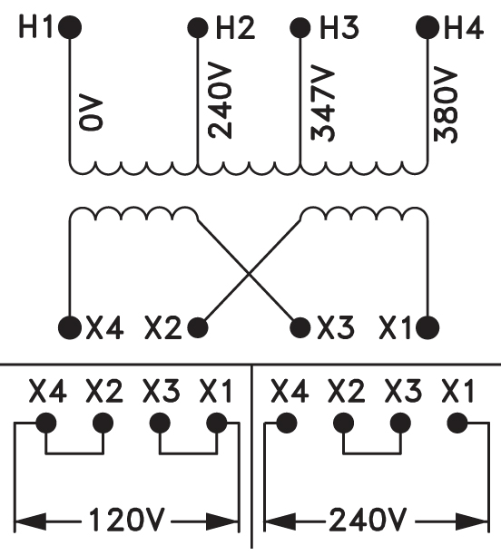
| RA SERIES | ||||||||||
|
|
 |
||||||||
|
Image is a general
representation of a typical MPC transfromer without fusing accessories or jumper links. Transformers 50VA - 350VA have 4 terminals per side and units 500VA and higher have 6 terminals per side. |
Wiring Diagram | ||||||||
| Approximate Dimensions and Weight | |||||||||
| Mounting Hole | Shipping | ||||||||
| VA Rating |
MPC Model # |
Max |
Max Width (B) |
Max Height (C) |
Mounting Depth (D) |
Mounting Depth (E) |
Depth | Width | Weight (lbs.) |
| 1,000 | MPC2-1H1K0RAU-FO | 6.23 | 7.00 | 5.65 | 4.00 | 6.13 | 0.31 | 1.06 | 29.80 |
| 1,500 | MPC2-1H1K5RAU-FO | 7.23 | 7.00 | 5.65 | 4.50 | 6.13 | 0.31 | 1.06 | 30.00 |
| 2,000 | MPC2-1H2K0RAU-FO | 7.98 | 7.00 | 5.65 | 5.13 | 6.13 | 0.31 | 1.06 | 38.00 |
| 3,000 | MPC2-1H3K0RAU-FO | 7.82 | 9.00 | 7.62 | 4.25 | 6.50 | 0.44 | 1.00 | 53.00 |
| 5,000 | MPC2-1H5K0RAU-FO | 8.81 | 9.00 | 7.62 | 7.25 | 7.50 | 0.44 | 1.00 | 89.00 |
| DS SERIES | ||||||||||
|
|
 |
||||||||
|
Image is a general
representation of a typical MPC transfromer without fusing accessories or jumper links. Transformers 50VA - 350VA have 4 terminals per side and units 500VA and higher have 6 terminals per side. |
Wiring Diagram | ||||||||
| Approximate Dimensions and Weight | |||||||||
| Mounting Hole | Shipping | ||||||||
| VA Rating |
MPC Model # |
Max |
Max Width (B) |
Max Height (C) |
Mounting Depth (D) |
Mounting Depth (E) |
Depth | Width | Weight (lbs.) |
| 50 | MPC2-1B050DSU-FO | 3.32 | 3.00 | 2.79 | 2.00 | 2.50 | 0.20 | 0.41 | 2.60 |
| 75 | MPC2-1B075DSU-FO | 3.82 | 3.00 | 2.79 | 2.50 | 2.50 | 0.20 | 0.41 | 3.50 |
| 100 | MPC2-1B100DSU-FO | 3.78 | 3.38 | 3.11 | 2.38 | 2.81 | 0.20 | 0.41 | 4.20 |
| 150 | MPC2-2B150DSU-FO | 4.27 | 3.75 | 3.42 | 2.88 | 3.13 | 0.20 | 0.41 | 6.70 |
| 200 | MPC2-2B200DSU-FO | 4.35 | 3.75 | 3.42 | 2.88 | 3.13 | 0.20 | 0.41 | 7.25 |
| 250 | MPC2-2B250DSU-FO | 4.55 | 4.50 | 4.04 | 2.88 | 3.75 | 0.20 | 0.41 | 10.0 |
| 300 | MPC2-2B300DSU-FO | 5.10 | 4.50 | 4.04 | 2.88 | 3.75 | 0.20 | 0.41 | 11.50 |
| 350 | MPC2-2B350DSU-FO | 5.28 | 4.50 | 4.04 | 3.75 | 3.75 | 0.20 | 0.41 | 13.60 |
| 500 | MPC2-2B500DSU-FO | 5.75 | 5.25 | 4.66 | 4.25 | 4.38 | 0.31 | 1.06 | 15.75 |
| EM SERIES | ||||||||||
|
|
 |
||||||||
|
Image is a general
representation of a typical MPC transfromer without fusing accessories or jumper links. Transformers 50VA - 350VA have 4 terminals per side and units 500VA and higher have 6 terminals per side. |
Wiring Diagram | ||||||||
| Approximate Dimensions and Weight | |||||||||
| Mounting Hole | Shipping | ||||||||
| VA Rating |
MPC Model # |
Max |
Max Width (B) |
Max Height (C) |
Mounting Depth (D) |
Mounting Depth (E) |
Depth | Width | Weight (lbs.) |
| 50 | MPC2-1B050EMU-FO | 3.23 | 3.00 | 2.79 | 2.00 | 2.50 | 0.20 | 0.41 | 2.60 |
| 75 | MPC2-1B075EMU-FO | 3.73 | 3.00 | 2.79 | 2.50 | 2.50 | 0.20 | 0.41 | 3.50 |
| 100 | MPC2-1B100EMU-FO | 3.69 | 3.38 | 3.11 | 2.38 | 2.81 | 0.20 | 0.41 | 4.20 |
| 150 | MPC2-2B150EMU-FO | 4.17 | 3.75 | 3.42 | 2.88 | 3.13 | 0.20 | 0.41 | 6.70 |
| 200 | MPC2-2B200EMU-FO | 4.35 | 3.75 | 3.42 | 2.88 | 3.75 | 0.20 | 0.41 | 7.25 |
| 250 | MPC2-2B250EMU-FO | 4.47 | 4.50 | 4.04 | 2.88 | 3.75 | 0.20 | 0.41 | 10.0 |
| 300 | MPC2-2B300EMU-FO | 5.10 | 4.50 | 4.04 | 2.88 | 3.75 | 0.20 | 0.41 | 11.50 |
| 350 | MPC2-2B350EMU-FO | 5.19 | 4.50 | 4.04 | 3.75 | 3.75 | 0.20 | 0.41 | 13.60 |
| 500 | MPC2-2B500EMU-FO | 5.17 | 5.25 | 4.66 | 4.25 | 4.38 | 0.31 | 1.06 | 15.85 |
| 750 | MPC2-2B750EMU-FO | 6.42 | 5.25 | 4.66 | 5.38 | 4.38 | 0.31 | 1.06 | 28.10 |
| 1,000 | MPC2-1H1K0EMU-FO | 6.21 | 7.00 | 5.65 | 4.00 | 6.13 | 0.31 | 1.06 | 29.80 |
| FN SERIES | ||||||||||
|
|
 |
||||||||
|
Image is a general
representation of a typical MPC transfromer without fusing accessories or jumper links. Transformers 50VA - 350VA have 4 terminals per side and units 500VA and higher have 6 terminals per side. |
Wiring Diagram | ||||||||
| Approximate Dimensions and Weight | |||||||||
| Mounting Hole | Shipping | ||||||||
| VA Rating |
MPC Model # |
Max |
Max Width (B) |
Max Height (C) |
Mounting Depth (D) |
Mounting Depth (E) |
Depth | Width | Weight (lbs.) |
| 1,000 | MPC2-1H1K0FNU-FO | 6.21 | 7.00 | 5.65 | 4.00 | 6.13 | 0.31 | 1.06 | 29.80 |
| 1,500 | MPC2-1H1K5FNU-FO | 7..98 | 7.00 | 5.43 | 5.13 | 6.13 | 0.31 | 1.06 | 38.00 |
| 2,000 | MPC2-1H2K0FNU-FO | 7.98 | 7.00 | 5.43 | 5.13 | 6.13 | 0.31 | 1.06 | 38.00 |
| 3,000 | MPC2-1H3K0FNU-*** | 9.00 | 9.00 | 7.62 | 7.25 | 7.50 | 0.44 | 1.00 | 89.00 |
| 5,000 | MPC2-1H5K0FNU-*** | 10.00 | 9.00 | 8.73 | 8.25 | 7.50 | 0.44 | 1.00 | 101.00 |
|
***No Fuse Kit is available for this model -Change end suffix for added options -Add C to suffix for the covers |
|||||||||
| ZP SERIES | ||||||||||
|
|
 |
||||||||
|
Image is a general
representation of a typical MPC transfromer without fusing accessories or jumper links. Transformers 50VA - 350VA have 4 terminals per side and units 500VA and higher have 6 terminals per side. |
Wiring Diagram | ||||||||
| Approximate Dimensions and Weight | |||||||||
| Mounting Hole | Shipping | ||||||||
| VA Rating |
MPC Model # |
Max |
Max Width (B) |
Max Height (C) |
Mounting Depth (D) |
Mounting Depth (E) |
Depth | Width | Weight (lbs.) |
| 50 | MPC2-1B050ZPU-** | 3.32 | 3.00 | 2.79 | 2.00 | 2.50 | 0.20 | 0.41 | 2.60 |
| 75 | MPC2-1B075ZPU-** | 3.82 | 3.00 | 2.79 | 2.50 | 2.50 | 0.20 | 0.41 | 3.50 |
| 100 | MPC2-1B100ZPU-** | 3.78 3.78 | 3.38 | 3.11 | 2.38 | 2.81 | 0.20 | 0.41 | 4.20 |
| 150 | MPC2-2B150ZPU-** | 4.27 | 3.75 | 3.42 | 2.88 | 3.13 | 0.20 | 0.41 | 6.70 |
| 200 | MPC2-2B200ZPU-** | 4.05 | 4.50 | 4.04 | 2.50 | 3.75 | 0.20 | 0.41 | 8.50 |
| 250 | MPC2-2B250ZPU-** | 4.55 | 4.50 | 4.04 | 2.88 | 3.75 | 0.20 | 0.41 | 10.00 |
| 300 | MPC2-2B300ZPU-** | 4.55 4.55 | 4.50 | 4.04 | 3.25 | 3.75 | 0.20 | 0.41 | 11.3 |
| 350 | MPC2-2B350ZPU-** | 5.28 5.28 | 4.50 | 4.04 | 3.75 | 3.75 | 0.20 | 0.41 | 13.60 |
| 500 | MPC2-2B500ZPU-FO | 5.75 | 5.25 | 4.66 | 4.25 | 4.38 | 0.31 | 1.06 | 16.10 |
| 750 | MPC2-2B750ZPU-FO | 7.00 | 5.25 | 4.66 | 5.38 | 4.38 | 0.31 | 1.06 | 28.10 |
|
**This model is not available with the FO
option (Consider F1) -Change end suffix for added options -Add C to suffix for the covers |
|||||||||
| ZZ SERIES | ||||||||||
|
|
 |
||||||||
|
Image is a general
representation of a typical MPC transfromer without fusing accessories or jumper links. Transformers 50VA - 350VA have 4 terminals per side and units 500VA and higher have 6 terminals per side. |
Wiring Diagram | ||||||||
| Approximate Dimensions and Weight | |||||||||
| Mounting Hole | Shipping | ||||||||
| VA Rating |
MPC Model # |
Max |
Max Width (B) |
Max Height (C) |
Mounting Depth (D) |
Mounting Depth (E) |
Depth | Width | Weight (lbs.) |
| 50 | MPC2-1B050ZZU-** | 4.44 | 3.00 | 3.45 | 2.38 | 2.81 | 0.20 | 0.41 | 4.20 |
| 100 | MPC2-1B100ZZU-** | 4.90 | 3.75 | 4.01 | 2.88 | 3.13 | 0.20 | 0.41 | 6.70 |
| 150 | MPC2-2B150ZZU-** | 4.58 | 4.50 | 4.64 | 2.88 | 3.75 | 0.20 | 0.41 | 10.00 |
| 250 | MPC2-2B250ZZU-** | 5.08 | 4.50 | 4.64 | 3.75 | 3.75 | 0.20 | 0.41 | 13.60 |
| 350 | MPC2-2B350ZZU-FO | 6.42 | 5.25 | 4.66 | 5.38 | 4.38 | 0.31 | 1.06 | 28.10 |
| 500 | MPC2-2B500ZZU-FO | 7.75 | 5.25 | 4.67 | 6.13 | 4.38 | 0.31 | 1.06 | 28.10 |
| 750 | MPC2-2B750ZZU-FO | 6.21 | 6.38 | 5.65 | 4.00 | 6.13 | 0.31 | 1.06 | 29.80 |
|
**This model is not available with the FO
option (Consider F1) -Change end suffix for added options -Add C to suffix for the covers |
|||||||||
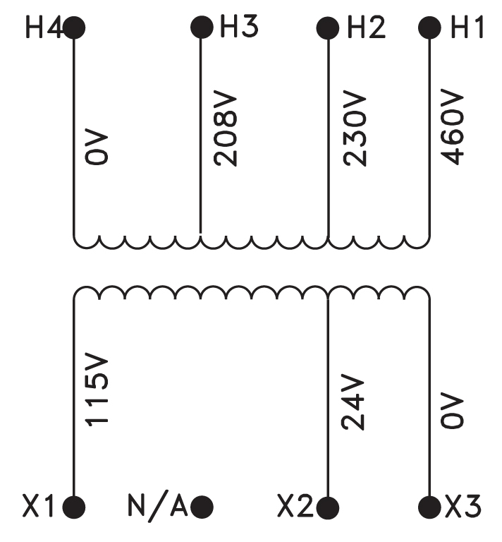
MPC VOLTAGE SERIES
MAG Power & Control Transformers are available in a wide variety of primary
and secondary voltages. If you do not see the voltage for you application
contact us for a quote on a custom transformer.
| Voltage Table | |||
| Series | Primary | Secondary | VA Sizes |
| DM | 220x440 230x460, 240x480 |
110 115 120 |
50 - 5000 |
| BS | 240x480 | 24 | 50 - 750 |
| AS | 120x240 | 24 | 50 -750 |
| BA | 240x480 | 120x240 | 50 - 5000 |
| WQ | 208/277 | 120 | 50 - 750 |
| CM | 200/220/440 208/230/460 /240/480 |
110 115 120 |
50 - 5000 |
| DY | 220x440 230x460 240x480 |
110x220 115x230 120x240 |
1000 - 5000 |
| CL | 200/220/440 208/230/460 /240/480 |
23/110 24/115 25/120 |
50 - 5000 |
| RA | 240/347/380 | 120x240 | 1000 - 5000 |
| DS | 115x230 | 24 | 50 - 500 |
| EM | 550 575 600 |
110 115 120 |
50 - 1000 |
| FN | 230/460/575 | 95/115 | 1000 - 5000 |
| ZP | 380/400/415 | 110x220 | 50 - 750 |
| ZZ | 600/480/416/240 575/460/400/230 550/440/380/220 500/ / /208 |
99/120/130 95/115/125 91/110/120 85/100/110 |
50 - 750 |
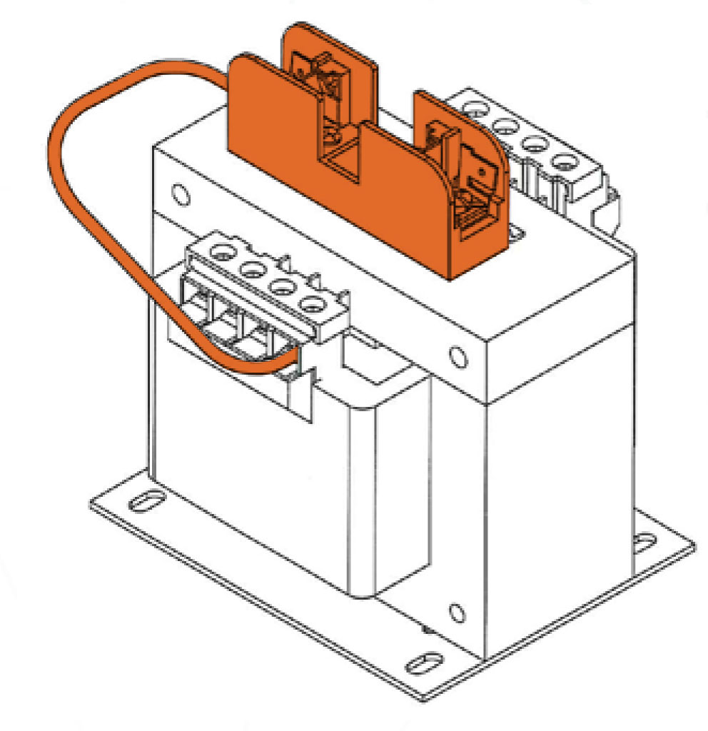
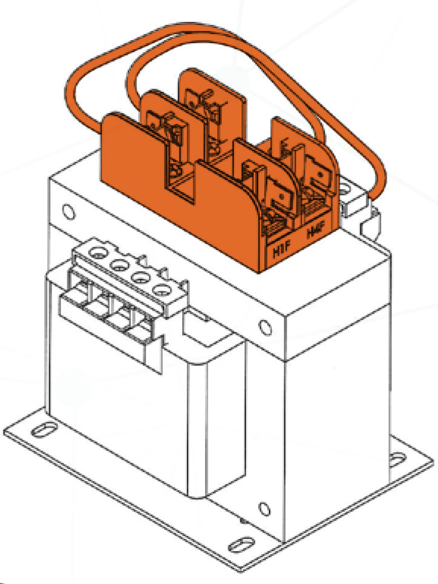
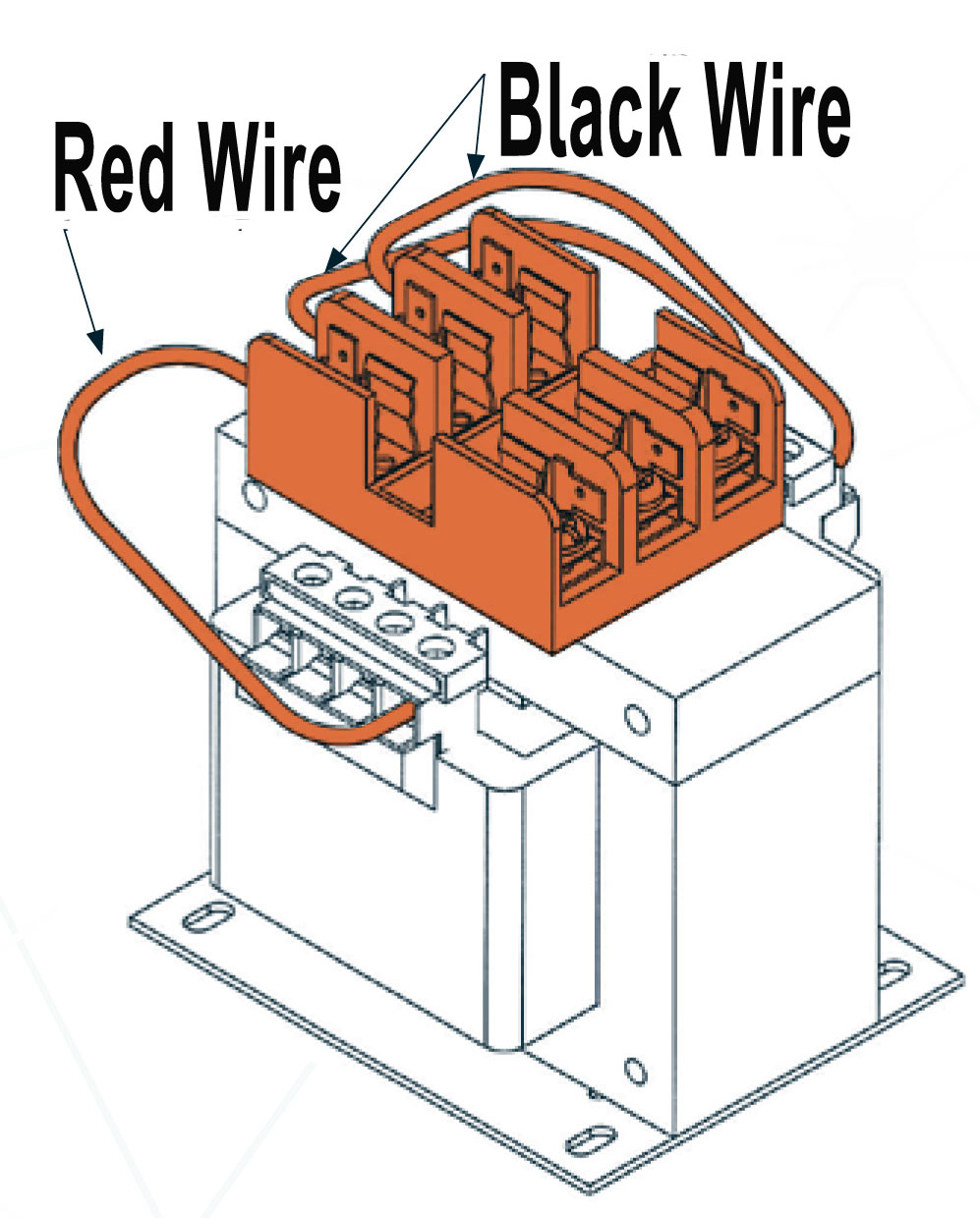
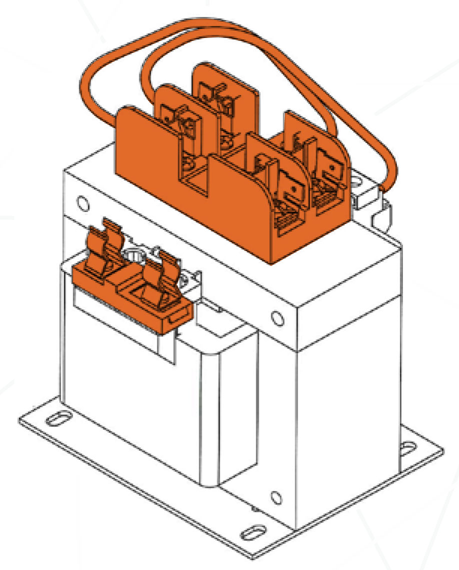
Fusing Options
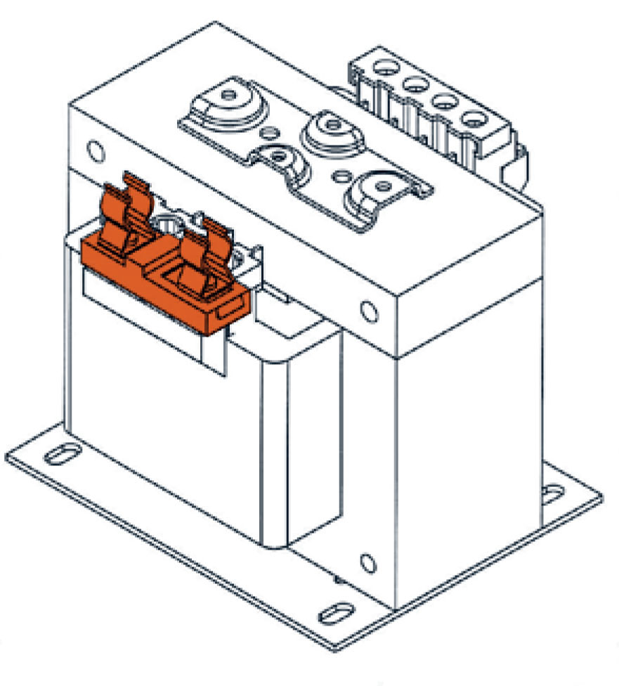
Option FO
Option F1
Option F2
Option F3
Option F4
|
Add to (MPC Part #) |
MPC Part (Ordered Separately) |
Fusing Options |
| C | MCP2-ACC-PFBCVK | PRI Fuse Cover Kit with puller |
| C | MCP2-ACC-SFBCVK | Secondary Fuse Cover Kit |
| FO | MCP2-ACC-FOB | Kit Secondary Fuse Clips (45VA-750VA) |
| FO | MCP2-ACC-FOH | Kit Secondard Fuse Clips (1KVA-5KVA) |
| F1 | MCP2-ACC-F1 | Kit Sec Fuse Block 1 - Midget |
| F2 | MCP2-ACC-F2 | Kit PRI Fuse Block 2 - CC |
| F3 | MCP2-ACC-F3 | Kit Fuse Block 2 - CC & 1 - Midget |
| F4 | MCP2-ACC-F4 | Kit Fuse Block 2 - CC & Clips |